The restoration of a 1980's Williams Defender arcade machine
Upgrading: Replacing the 4116 memory with 4164 memory
It’s a well documented fact that the standard 4116 memory used for the Williams games such as Defender gets very hot and fails often, and also requires multiple voltages to work, which make them a hassle to maintain
One common upgrade is to replace the 4116 memory (64k memory needing +5V, -5V and +12V) with 4164 memory (64k memory needing only +5V), but there are multiple ways of doing it.
Here’s a summary of the options and some links and pictures:
1. Modify the CPU board to re-route the +5V and disconnect the -5V and +12V
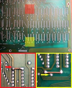
A neat solution from Matt Osborn involving minimal soldering and a couple of cut jumpers
- Cut the trace indicated by the red arrow. This removes the +12V supply to all of the RAM (and only the RAM).
- Solder the link as shown. This will supply +5V where it is needed on the new RAM.
- Cut the trace indicated by the yellow arrow. This removes the -5V supply to all of the RAM.
- [This step is optional] Solder the link as shown. This will allow you to use 41256 as well as 4164. This grounds the additional address line (pin 1) on the larger capacity 41256 (this pin is unused on the 4164). With this mod in place you can mix and match 4164 and 41256. The board pictured is running MK4564, TMS4256, and HM50256. There are many more 64k*1 and 256k*1 chips that fit the bill.
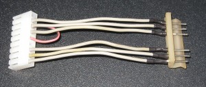
2. Build an adapter to re-route the +5V and disconnect the -5V and +12V
A couple of good options here
Dave Langley’s neat adapter
and two options from the guys on arcadecontrols.com
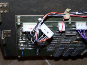
3. Add an extra plug to your game harness
A neat trick from ‘dokert’ over on KLOV is to add an extra 4164 connector to the main cabinet harness, and then you can switch as you like!
[Update: 20/02/2018] Looking back at this option to modify my own cabinet I couldn’t find the original post so mapped out the wiring changes needed to add the extra plug to the cabinet
Normal (4116)

1 N/C
2 GND
3 GND
4 Key
5 +12V DC Reg
6 N/C
7 +5V DC
8 +12V DC UnReg
9 -5V DC

Extra 9-pin Connector (4164)

1 N/C
2 GND
3 GND
4 Key
5 +5V DC
6 N/C
7 +5V DC
8 +12V DC UnReg
9 N/C
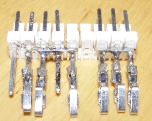
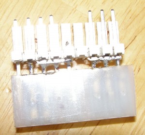
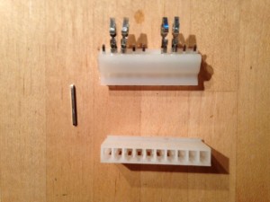
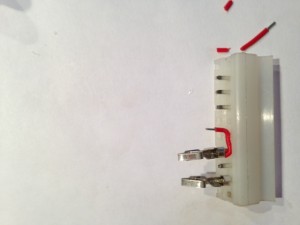
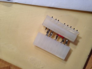
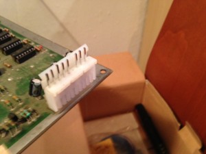
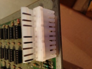
4. A couple of molex plugs, some molex crimp pins and a small wire jumper
and finally here’s my version using a couple of molex plugs, and a small wire jumper – very fiddly to do but works just fine 🙂
[note: the pins are in the wrong order in the photo above – the jumper should be from 3 – 5]
| Print article | This entry was posted by Judder on December 17, 2014 at 5:51 pm, and is filed under The Boards, Williams Defender restoration. Follow any responses to this post through RSS 2.0. You can skip to the end and leave a response. Pinging is currently not allowed. |
about 10 years ago
Who can fix my Stargate board? Thanks
about 6 years ago
Thank you for documenting this. It is saving my bacon when piecing together changes I made a decade ago to my defender machine. Thanks to this site Defender will live again.