The restoration of a 1980's Williams Defender arcade machine
Tron: Testing the Audio Amplifier
I’ve been struggling with the sound in our Tron for a few weeks now, so decided to isolate the external sound amplifier and test it, to prove whether it was working or not.
Thought that it would be helpful for all the other Tron owners to document how to do this – and a handy video at the end showing ‘new’ Tron meet ‘old’ Tron – the irony maybe lost on some 🙂
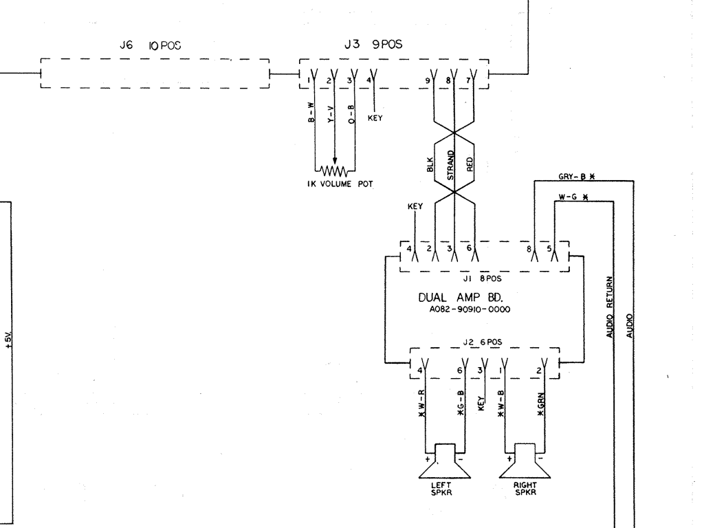
1. Schematics
So the sound amp takes stereo input from the Super Sound I/O board, and 12V power, and then outputs to a pair of speakers to give the ‘stereo’ output that the game uses.
We need to rig up:
1.J3 (Input)
- pin 2- audio left
- pin 6 – audio right
- pin 3 – ground
To do this I used a headphone jack that was rescued one morning on the way to work and simple soldered 3 wires to the pins on the headphone jack connector
- pin 5 – Ground (Audio Return)
- pin 8 – +12V DC (Audio)
I’m using a simple switching power supply, but any +12V would do
2. J2 (Output)
- pin 1 – audio left +ve
- pin 2 – audio left -ve
- pin 4 – audio right +ve
- pin 6 – audio right -ve
Here’s the relevant part of the schematics for reference.
Setup:
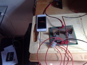
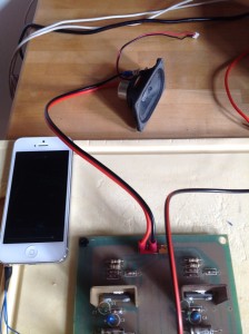
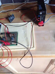
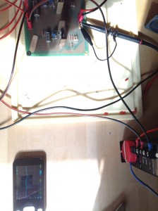
Here’s a picture of how I set things up
Audio from iPhone into stereo back into pins 2, 3 and 6
Speaker (just testing one channel at the moment)
Power (note the milk bottle top – it makes a handy ‘safety’ for the 240V coming in the front if you cut a couple of channels in it for the wires with a Stanley knife 🙂
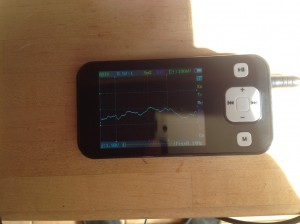
You can also test the audio output with an Oscilloscope
Here’s it running with the nifty and very reasonably priced DSO201 Android based scope with settings 0.5V (Y-Axis) and .5ms (X-Axis)
and here it is all running together with some suitable test music
Tron Arcade Machine Sound Amplifier Test Rig from Alex Judd on Vimeo.
| Print article | This entry was posted by Judder on August 10, 2014 at 4:49 pm, and is filed under Audio, Tron restoration. Follow any responses to this post through RSS 2.0. You can skip to the end and leave a response. Pinging is currently not allowed. |
about 11 years ago
Important update on the above – in the write up I had the +12V and the Ground switched around
Just proved that by testing a board in the cabinet, wired it the wrong way round = smoke and smell of burning electronics
Luckily second replacement amp works fine, and I now need to go and fix the first one that _was_ working fine.
My guess is that it blew the two MB3730 audio power amplifiers – anyone done this before???