The restoration of a 1980's Williams Defender arcade machine
Testing: How to basically test your Defender board set
From a post I wrote on UKVac to hopefully help another user
“Is anyone on here able to test my defender boardset for me? It shows lines down the screen and has never booted properly and the old owner said the sound had failed before I bought it.”
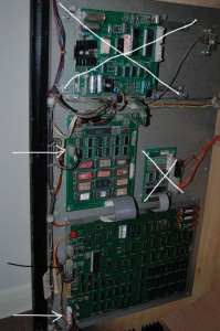
The sound board and the interface boards are totally separate, so you can rule those out of the question for the moment (crosses on the shot below)
If you are getting vertical lines that (for me) was normally where power wasn’t getting to the ROM board correctly as the connection was loose.
Check the two connections with the white arrows in this picture (the ROM board is the middle board, the CPU board the bottom board) and make sure you have +5v, -5v and +12v coming through correctly as per the Defender Interboard Wiring Diagram (in the manuals on Dave’s site).
I’ve had issues where the +5v to the ROM board was a flakey connection and the game just gave me vertical bars.
If you are getting power fine, then check the monitor connection (middle lead with black arrow) to ensure that the output is going to the monitor (just do a simple connectivity test from the board pin with the plug connected to the monitor plug RGB Sync.)
If you have power and monitor connected correctly you should get what they call a ‘Rug’ pattern on the screen, scrolling left to right as the machine initiates.
A ‘rug’ patter looks like random coloured pixels all over the screen 🙂
| Print article | This entry was posted by Judder on March 19, 2014 at 2:59 pm, and is filed under The Boards, Williams Defender restoration. Follow any responses to this post through RSS 2.0. You can skip to the end and leave a response. Pinging is currently not allowed. |
