The restoration of a 1980's Williams Defender arcade machine
Testing: Building a Williams Test Rig (part 1 – board layout)
In order to test our Williams CPU, ROM, I/O and Sound boards I’ve decided it’s time to invest some time and effort and build a complete Williams Test Rig.
The goals of the rig are:
– Allow testing of all Williams boards (CPU, ROM, I/O, Sound)
– Allow testing of all Williams games (Defender, Stargate, Joust, Robotron, etc.)
– Be easily store-able
– Not need an arcade monitor to test
Ingredients:
Mounts
1 x plank of wood to host the boards
1 x pack of RS Electronics PCB mounts and screws
Power
1 x Linear power supply for desk testing
1 x ATX Power Supply Male and Female connector (for easily switching between the linear power supply and the original power connector)
Video
1 x CGA to VGA connector to SVGA connector from eBay ($6.95)
1 x SVGA to SVGA lead
1 x RGB to SVGA upscaler from eBay ($22.49)
1 x SVGA to SVGA lead (to monitor)
1 x SVGA monitor
Wiring
1 x Williams Defender wiring harness (from sadly deceased machine someone else broke via eBay US)
1 x extra combined Sync wiring to pin 7 of the Williams video connector
1 x Sound -> Rom connector
1 x Volume POT
1 x Speaker
1 x Williams Defender control panel wiring (from same sadly deceased machine above)
Game
1 x Williams Defender ROM, CPU, Sound and I/O Board
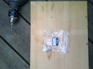
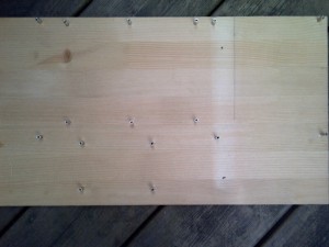
Step 1: Mark the board positions and drill holes for mounting screws.
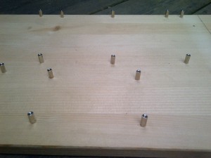
Step 2: Screw in the PCB mounting screws
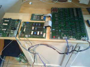
Step 3: Add the Williams Defender boards and start connecting up the wiring harness
Continued in Part 2 ->
| Print article | This entry was posted by Judder on April 29, 2014 at 4:49 pm, and is filed under Testing, The Boards, Williams Defender restoration. Follow any responses to this post through RSS 2.0. You can skip to the end and leave a response. Pinging is currently not allowed. |


