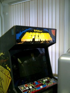
The restoration of a 1980's Williams Defender arcade machine
Power Supply Rebuild [complete]
So I’ve decided to fight my fear of 240V mains electricity and put some trust in my rebuilding of the Transformer and Power Supply board and plug it in and start doing some output voltage measuring.
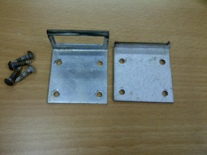
First thing was to replace the broken bracket that holds the cut-off switch for the cabinet back-cover being removed, as the old one had been snapped way before I got the machine, and my replacement had arrived from the US
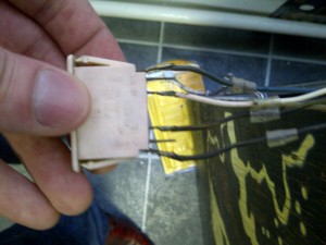
The problem is that the cut-off switch has to be inserted into the bracket from the _front_ however the wires are soldered to the _back_ of the switch so we’re going to need to de-solder them and either re-solder or put crimp plugs on instead (*much easier IMHO)
and the new versus old brackets
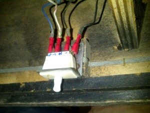
and all wired up with crimp plugs and back in place (note the 4,3,2,1 written to match up the leads with their positions 🙂 )
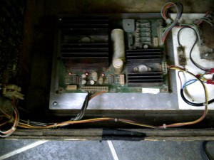
So, now that we have the wiring all correctly in place, let’s replace the Power Supply board in the base of the cabinet, override the cut-off switch by pulling it outwards (n.b. the cabinet back should push in to do the same, but we don’t have a cabinet back at this point…) and connect up the power plug to the mains (with a long extension lead).
Standing a good 6 foot away (*just in case) it’s time to finally give all of our hard work some power and see what happens…
Lights!!!!!
That’s probably the first time I’d say in at least 6/7 years that this machine has done anything near work, and seeing as it’s now on a different continent, powered by a different 240V on a rebuilt PSU that’s pretty amazing 🙂
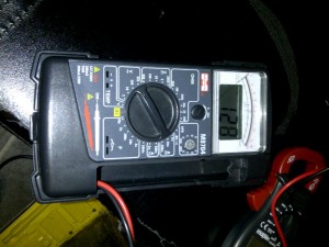
So let’s be a bit brave and see if we can measure the voltage that should be going to the monitor before we plug that in. It should 125V so turn everything off, connect the multi-meter to the two outputs from the monitor plug power supply unit socket (as the current is AC they can be either way around) and turn on from the other side of the room…
128V 🙂 Perfect so we can connect that too.
Last check for this phase is that the Power Supply board has it’s 3 voltage check lights on.
The should show that it is generating +5V, -5V and +12V correctly.
So that’s all looking good.
Last job is to measure the voltages that are going out to the game boards to make sure they are as accurate as the LED lights suggest.
To do this you unplug the J2 connector (bottom plug in the middle of the green board above, underneath the 2 right lit LED lights) and measure according to this handy guide from www.coinop.org
Black (negative) on the multi-meter to pin 8 (that’s 8 from the right as 1 is the furthest right)
4J2-8 = Reference ground
and then tested
4J2-12 = +5.07 (should be +5VDC)
4J2 – 3 = +11.47 (should be +12VDC regulated)
4J2 – 5 = +14.50 (should be +12VDC unregulated)
4J2 – 1 = -5.04 (should be -5VDC)
4J2 – 4 = -14.85 (should be -12VDC unregulated)
So the + and -5V seems to be pretty spot on, the +12V a little low (but OK I would have thought in limits and fits) and the + and – 12VDC unregulated seem to be high.
The learned fellows on UKVAC highlighted that the unregulated +/- 12 V supplies are fine, as the boards/components will only pull as much as they want from that, so even though it is over 12V they won’t mind 🙂
Power supply – DONE.
Next steps – let’s see what the boards do and getting the game to work
| Print article | This entry was posted by Judder on May 13, 2012 at 2:57 pm, and is filed under Power Supply Unit, Williams Defender restoration. Follow any responses to this post through RSS 2.0. You can skip to the end and leave a response. Pinging is currently not allowed. |
